Product Category Mechanical Power Transmission Product Locking Assembly Canto-Lock - C-1018, UsageApplication Industrial
Active
Premium
Key Highlights
₹ 2639.00
per Piece (pcs)
MOQ
1
Available Variants
Technical Specifications
| Parameter | Value |
|---|---|
| Size | 14 mm to 50 mm |
| Brand | NMTG |
| Model | N7134 |
| Weight | 0.5 kg to 0.8 kg |
| Material | Alloy Steel |
| Operated By | NMTG |
| Applicable For | Various Industries |
| Packaging Type | Wooden / Box |
| Product Category | Mechanical Power Transmission Product |
| Country of Origin | Made in India |
| Quantity Per Pack | 1 |
| Surface Finishing | Yes |
| Usage/Application | Industrial |
Product Description
Compatible Locking Assemblies for Industrial Mechanical Power Transmission Machines
Product features self centering high torque shaft size 100mm to 400mm torque 14400nm to 535000nm recommended mounting tolerances shaft h8 our specifications for rod and hub bore surface finish available in, Are ra inch measurements series also instruction 1 surface finish require for shaft and hub bore ra2 recommend mounting shaft h8 for hub h8 erance for3 Refrain from applying lubricants; it features a molybdenum disulfide formulation by Molykote oil. Installation and removalinstructions for canto, Lock locking assembly series c, 1018 & 1018. 1canto, Lock c, 1018 & 1018. 1 locking assemblies are delivered set up for installation. If the unit should confirm that, Be dismantled together with lined, Up slits in near and, All collars farside clamp collars are not reversed. They are assembled correctly if there are no holes or threads behind taps in clamp collar item 2 and no threads behind taps in center collar item 1 . Moreover, The rings are marked. Be sure that these marks are aligned. The torque capacity of this device draws from a coefficient of friction of u=0. 12 for lightly oiled screws, Tapers, Shaft and hub contact It holds, Areas. Therefore significant value not to use molybdenum disulfide e. G., Molykote, Never, Seeze or similar lubricants in any locking assembly installation. Installation1. Make sure that locking screws, Rings, Shaft and hub contact surfaces are clean and lightly oiled and that all collar slits and marks are aligned. 2. Loosen all screws by minimum 2 turns and transfer at least 2 screws into push, Off threads in clamp collar item 2 and center collar item 1 for the aim of disengage tapers Crafted for hassle-free installation of locking assembly. 3. After installation of relocate locking, Locking assembly screws used for separation of collars. 4. Hand tighten the connection and assure that collars item 2 and 3 are parallel5. Employ the torque wrench and calibrate it to about 5% Surpassing the designated requirements torque applied for tightening . Torque screws in a using only, Crosswise pattern 1/4 operates through several rotations until it can no longer complete 1/4 turns. Furthermore, Apply overtorque for one or two additional rotations is necessary to compensate f a structure focused on stress relief ocking screws since tightenin f a particular screw consistently will relax adjacent screws without overtorquing A limitless series of turns is essential to attain the targeted tension torque. 7. Reset torque wrench to specified forque ts and check all locking screws. No screw should turn at this point, Otherwise repeat step 6 ideal for an extra person or two passes Rechecking the tightening torque after equipment installation is unnecessary in operationnote for installation subjected to extreme corrosion the slits should be sealed with a suitable caulking compound or equivalent. Likewise, Push, Offthreads should also be protected from corrosionremovalnote Ensure there are no obstacles before proceeding with the removal procedure below torque or th rust loads are performing on the locking assembly, Bar or any other mounted components1. Check to guarantee that axial movement of clamp collars, Necessary for release of connection is not restricted likewise, Ensure that push, Off threads are in good conditions. 2. Loosen all locking-type screws and transfer some into all push, Off threads in clamp collar item 2 see fig. 2 3 release collar item 2 by tightening all push, Off screws in a capped at, Diagonal arrangement 1/4 turns for several passes. 4. Transfer locking screws used for dismounting of clamp collar item 2 into all push, Off threads in center collar item 1 see sg. 3 release clamp collar item 3 by repeating procedure outlined in step 3.
Shipping Information
Availability
In Stock
Price
Excluding all taxes
Ships from
Pune
Delivery Location
All India delivery available
Shipping
As per delivery location
Seller Information
P
P. B. Traders
Verified
Pune, Maharashtra, India
Established:
2016
Delivery Time:
60+ Business Days
Shipping Options:
Trust & Safety
Trade Assurance Protected
Secure Payment Methods
Logistics Tracking Available
24/7 Customer Support
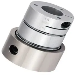
Material STEEL Locking Assemblies CHENNAI, Packaging Type STD, Brand KBK GERMANY
₹ 1478.00
per Piece (pcs)
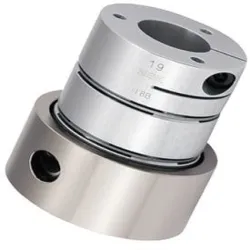
Precision Locking Element, Color Name Golden, Material StainlessMild Steel, Brand Tanatan
Request Price
per Piece (pcs)
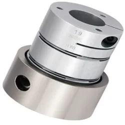
Shrink Discs Locking Assemblies, Color Black, Material StainlessMild Steel
Request Price
per Piece (pcs)
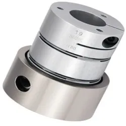
Color Silver, Finish Polished High Gain Type Coupling, Pin Length 4inch, Pin Diameter 1mm
₹ 297.00
per Piece (pcs)